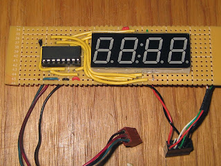
Here is a wooden alarm clock I made using the ATMega328 micro-controller, programmed with the Arduino IDE. For the time keeping I used a DS1307 RTC with a Li-ion rechargeable battery on a trickle charger. the battery is used to keep the time even when the clock is unplugged. If the power goes out or the clock needs to be moved it will still display the right time when power is reconnected. I believe the data sheet for the RTC (Real Time Clock) says that on full charge of the battery, it will maintain it's charge for 5 years before needing to be charged again. The five buttons on the top from right to left are as follows: ALARM SET, TIME SET, SNOOZE, HOUR, MINUTE. There is a switch on the left side which is used for turning the alarm on and off. There are two LED's at the top of the face the left one is orange and represents the alarm being on, and the right LED represents PM. Over The coarse of this project I was able to introduce myself to a ton of new things I will be able to use in so many more projects.
When I very first started to work on my clock I had nothing but a blue display and an Arduino UNO Dev Board. The display wasn't even meant for displaying time. There was no colon in between hours and minutes. The displays I used are multiplexed together. all of the Positives of each seven segment display are connected and each segment has it's own Ground. What I did for this in my programming was cycle through which ground is connected 1 at a time. Apparently most 7 seg displays are this way. only one display or one LED is on at anytime. They are switched on and off so fast that the human eye cant see the change. The time keeping was done all inside the microcontroller which I found to be very difficult and almost impossible to stay accurate. So the first two changes that were made were a new display which featured the colon separator, and the DS1307 RTC for keeping time accurately.
Above you can see, between the Arduino and the breadboard on the right, is the RTC. And the display is now sporting the nice and shiny colon that was so important. Just thought I would add in, I would have used a different color for the display but when i was looking for one on Ebay, Kelly wanted to know if I could get it in blue.
The RTC is interfaced to the ATmega through an I2C bus consisting of two wires plus power and ground. Also in this picture you can see I started to add an LED and a couple buttons. The LED was the PM indicator. The two buttons are normally open Momentary switches I used them to test the changing of Hours and Minutes. I want to add in right now that if anyone is planning on ever doing anything with switches and digital logic I cant stress enough the importance of Pull Down Resistors and Debounce Functions. Thank God my friend Joe is a programming wizard and made me my very own Button Library to use with future projects. In fact Joe helped me out with a huge portion of the programming and it would have taken me a lot longer to learn some of the tricks he threw in there.
Here I cleaned up the breadboard some and also added a 74HC595 serial in parallel out Shift Register. The shift register was needed to expand my i/o on the microcontroller. I wouldn't have enough after the Buzzer, LED's, and Set buttons were added. I used the shift register only for the display. Before the display used up 8 i/o plus 4 i/o for the grounds. Now I reduced it to 3 plus the 4 transistors switching the grounds.
Now After Finally having tested everything and breadboarding was complete it was time to make some circuit boards. I used graph paper to lay out the real estate for the parts and connectors. I had to make sure none of the traces would be touching. however I did end up using much more jumper wires than I thought I would.
The three main boards were the motherboard, which contained the power input/regulator, everything the ATmega328 controller needed to run, And some connectors I ripped from an old computer to use to connect to the other parts. I used a linear regulator for the input power. These are inefficient and waste a lot of power depending on the source. but I wanted to make sure everything fit and that a stable 5 volts would be available. Because of how they work, if you try to drop anything from 9 - 24 volts down to 5 through the regulator the regulator will get very hot. So on the top right of the motherboard I added a heat sink. I'm using a 6 volt supply so right now the reg doesn't get hot at all.
The back of the boards are kind of ugly. I didn't actually print any of the circuit boards. I used perf board from radio shack and used very thin wire to make the traces. I am in the process of learning EAGLE CAD to design my PCB's and have them professionally printed at a board house. It will be nice once I'm comfortable knowing my Gerber files for cad are actually sized the way i need for everything because making boards the way I did is a royal pain in the ass.
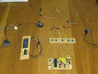
Here is all the hardware for the clock. I am a firm believer that you should never build anything you cant take apart later. So I made all the wires just a bit longer than needed and also added connectors so every part can be connected and disconnected with ease.
The wood I used is Oak for the three thicker layers and teak for the darker, smaller two layers. The teak came from a close out of flooring at a sorry excuse for a home improvement store I worked at a few years ago. I wanted the Clock to be as small as possible. This is why everything on the motherboard is so close together. I made the wood just big enough to fit the motherboard. All five pieces of wood were cut to exactly the same length and width. I slowly cut out the centers of the wood to fit the various parts.
I'm pretty happy with how everything was able to fit into the enclosure. There isn't any wiggle room for the parts. The only thing that might be a pain to get out if I have to fix it is the RTC and the switchboard. The RTC is hot glued in place to the side of the box and the switchboard was built all in one with the top of the box and then that was glued on with wood glue.
Here it is turned on while the glue is drying. The LED's at the top are behind a 1/4 layer of hot glue that is actually flush with the rest of the face because of sanding. I did this on another project and It turns out pretty good.
After it was done gluing I sanded it down nice and smooth, rounded over all the edges and prepared it for the polyurethane.
I don't have a picture of the bottom of the clock but on the bottom is another very thin layer of teak with 4 screws holding it in place on the bottom of that I glued on 4 rubber feat to keep it from easily sliding on whatever it may be sitting on.
Finished. I have been working on this clock for about 2 months. I originally wanted to give it to my girlfriend Kelly for her birthday in November but it didn't end up being completed until mid December. So I wrapped it up for Christmas instead. I spent very little money on this because I didn't have any money to spend. Like I said, most parts were pulled from broken junk I had laying around and scrap wood in the garage the most expensive part was the 7 segment LED display which was a whopping $4.00. So happy with the Project. Spent a ton of time working on it. and I learned a whole lot. So if you liked it please comment and let me know. Thanks and Merry Christmas.
Here's a link to the code: Clock sketch


That is Really Cool.
ReplyDeleteVery cool. I'm working on a project kind of like this. I don't suppose you'd consider sharing your code? I'm looking to optimize my clock.
ReplyDeleteYeah you can see my code. I will put a link at the bottom of my post.
DeleteGreat job! Always awesome to see a project clear through to completion.
ReplyDeleteDude this is awesome! You should totally build/sell custom electronics like this
ReplyDeleteThank it's good project I from SMKN Rajapolah Tasikmalaya INDONESIA
ReplyDeletewhich software version are you using because I could not compile this
ReplyDeleteI tried different versions of arduino ide but could compile this please help me any one
ReplyDeleteWow, you are the first one that has asked. I realize I have a library (button.h) that I didn't include. My friend and I wrote this library. I will try to post it below the other link later today or tomorrow. Thanks for trying it out.
Delete